Solution Found!
The variable resistor (R ) in the circuit in Fig. P4.88 is
Chapter 4, Problem 4.87(choose chapter or problem)
QUESTION:
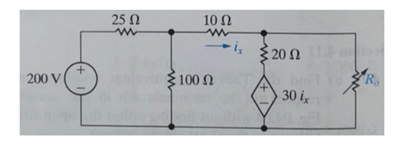
The variable resistor (R ) in the circuit in Fig. P4.88 is adjusted until the power dissipated in the resistor is 250 W. Find the values of R that satisfy this condition. Figure P4.88
Questions & Answers
QUESTION:
The variable resistor (R ) in the circuit in Fig. P4.88 is adjusted until the power dissipated in the resistor is 250 W. Find the values of R that satisfy this condition. Figure P4.88
ANSWER:Step 1 of 4
The given circuit diagram is,
To convert the voltage source 200 V into current source 

The modified circuit is drawn below,
