Solved: A sequential circuit of the form shown in Figure
Chapter 13, Problem 13.26(choose chapter or problem)
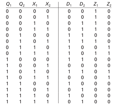
A sequential circuit of the form shown in Figure 13-17 is constructed using a ROM and two D flip-flops. The contents of the ROM are given in the table.
(a) Draw a timing diagram for the circuit for the input sequence \(X_{1} X_{2} = 10, 01, 11, 10\). Assume that input changes occur midway between rising and falling clock edges. Indicate any false outputs on the diagram, and specify the correct output sequence for \(Z_1\) and \(Z_2\).
(b) Construct a transition table and state graph for the circuit.
Unfortunately, we don't have that question answered yet. But you can get it answered in just 5 hours by Logging in or Becoming a subscriber.
Becoming a subscriber
Or look for another answer