Solution: The shaft shown in the figure is proposed for the
Chapter 7, Problem 7-21(choose chapter or problem)
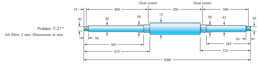
The shaft shown in the figure is proposed for the application defined in Prob. 3–73, p. 152. The material is AISI 1018 cold-drawn steel. The gears seat against the shoulders, and have hubs with setscrews to lock them in place. The effective centers of the gears for force transmission are shown. The keyseats are cut with standard endmills. The bearings are press-fit against the shoulders. Determine the minimum fatigue factor of safety using the DE-Gerber failure criterion.
Unfortunately, we don't have that question answered yet. But you can get it answered in just 5 hours by Logging in or Becoming a subscriber.
Becoming a subscriber
Or look for another answer