Solution Found!

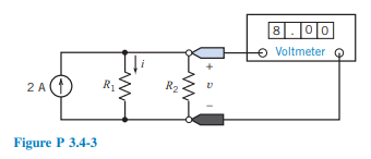
The ideal voltmeter in the circuit shown in Figure P 3.4-3 measures the voltage v. (a)
Chapter 3, Problem P 3.4-3(choose chapter or problem)
The ideal voltmeter in the circuit shown in Figure P 3.4-3 measures the voltage v.
(a) Suppose \(R_2=6 \Omega\). Determine the value of \(R_1\) and of the current i.
(b) Suppose, instead, \(R_1=6 \Omega\). Determine the value of \(R_2\) and of the current i.
(c) Instead, choose \(R_1\) and \(R_2\) to minimize the power absorbed by any one resistor.
Questions & Answers
QUESTION:
The ideal voltmeter in the circuit shown in Figure P 3.4-3 measures the voltage v.
(a) Suppose \(R_2=6 \Omega\). Determine the value of \(R_1\) and of the current i.
(b) Suppose, instead, \(R_1=6 \Omega\). Determine the value of \(R_2\) and of the current i.
(c) Instead, choose \(R_1\) and \(R_2\) to minimize the power absorbed by any one resistor.
ANSWER:
Step 1 of 5
(a)
Redraw the given circuit.
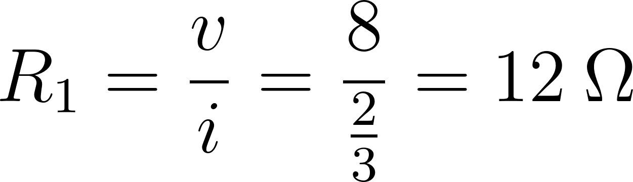
Applying Ohm’s law to the resistor 

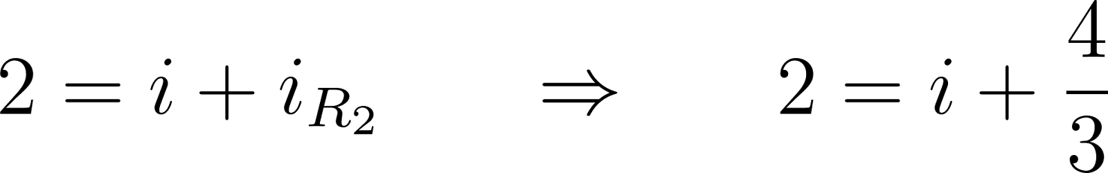
Applying KCL to the upper node gives

Applying Ohm’s law to