Solution Found!

The circuit shown in Figure P 16.4-5 is a lowpass filter. The transfer function of this
Chapter 16, Problem P16.4-5(choose chapter or problem)
QUESTION:
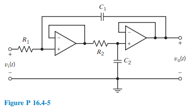
The circuit shown in Figure P 16.4-5 is a low pass filter. The transfer function of this filter is
\(H_{\mathrm{L}}(s)=\frac{\frac{1}{R_1 R_2 C_1 C_2}}{s^2+\frac{1}{R_1 C_1} s+\frac{1}{R_1 R_2 C_1 C_2}}\)
Design this filter to have \(k=1, \omega_0=1000 \mathrm{rad} / \mathrm{s}\), and Q = 1.
Questions & Answers
QUESTION:
The circuit shown in Figure P 16.4-5 is a low pass filter. The transfer function of this filter is
\(H_{\mathrm{L}}(s)=\frac{\frac{1}{R_1 R_2 C_1 C_2}}{s^2+\frac{1}{R_1 C_1} s+\frac{1}{R_1 R_2 C_1 C_2}}\)
Design this filter to have \(k=1, \omega_0=1000 \mathrm{rad} / \mathrm{s}\), and Q = 1.
ANSWER:
Step 1 of 2
We have to answer problem 45 and 46 for entropy