Solution Found!
The three loads in the circuit seen in Fig. P10.24 are
Chapter 10, Problem 10.24(choose chapter or problem)
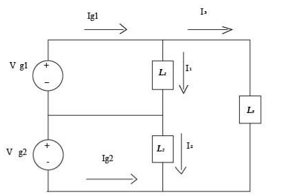
The three loads in the circuit seen in Fig. P10.24 are described as follows: Load 1 is absorbing 4.8 kW and delivering 2.4 kVAR; Load 2 is absorbing 6 kVA at a power factor of 0.8 lagging; Load 3 is a 24 resistor in parallel with an inductance whose reactance is . a) Calculate the average power and the magnetizing reactive power delivered by each source if Vg1 = Vg2 = 120l0 V (rms) b) Check your calculations by showing your results are consistent with the requirements aPdev = aPab aQdev = aQabs.
Questions & Answers
QUESTION:
The three loads in the circuit seen in Fig. P10.24 are described as follows: Load 1 is absorbing 4.8 kW and delivering 2.4 kVAR; Load 2 is absorbing 6 kVA at a power factor of 0.8 lagging; Load 3 is a 24 resistor in parallel with an inductance whose reactance is . a) Calculate the average power and the magnetizing reactive power delivered by each source if Vg1 = Vg2 = 120l0 V (rms) b) Check your calculations by showing your results are consistent with the requirements aPdev = aPab aQdev = aQabs.
ANSWER:Step 1 of 4
The three loads in the circuit.
Load 1: is absorbing 

Load 2: is absorbing 

Load 3: is a 

Draw the circuit as,