Shown in Fig. P13.11D is the schematic of a cogeneration
Chapter 13, Problem 13.11D(choose chapter or problem)
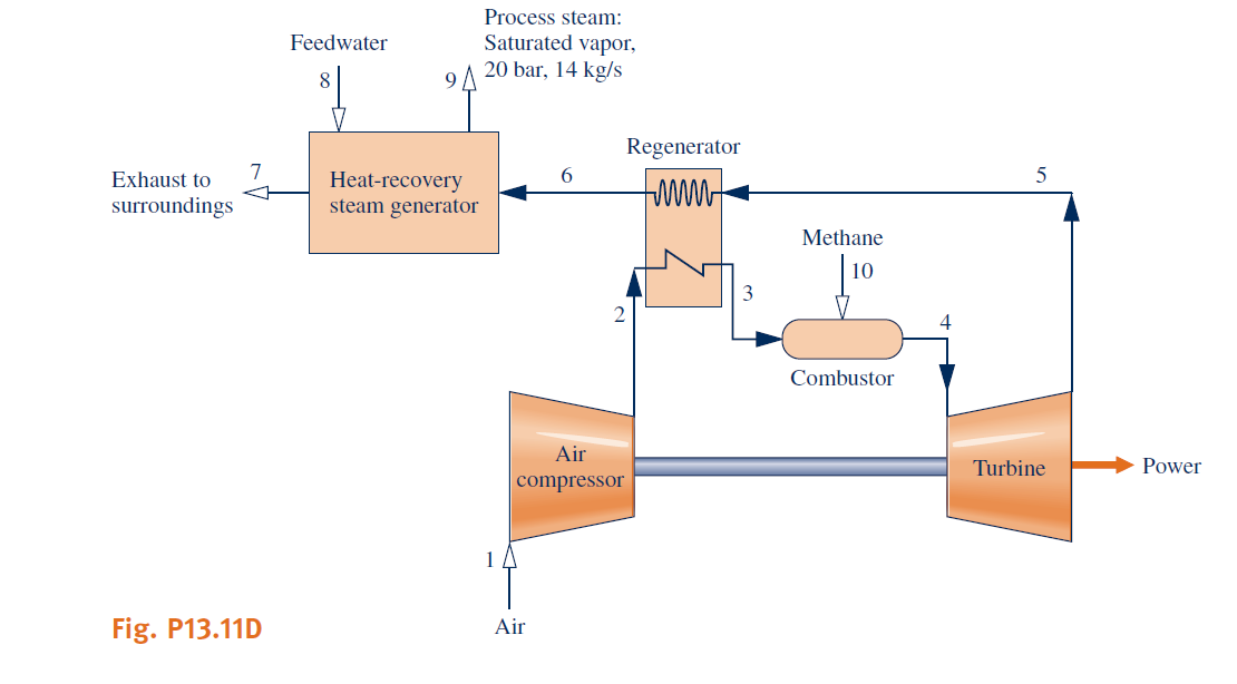
Shown in Fig. P13.11D is the schematic of a cogeneration system providing both power and steam. Develop a full exergy accounting of the exergy entering with the fuel. Evaluate the exergetic efficiency of each system component and the overall cogeneration system. Using these results, identify tweaks to the given system promising greater overall exergetic efficiency. Present your analyses, results, and recommendations in a technical article adhering to ASME standards with at least three references.
The six-point engineering model to follow, which is based on a previous concept development design effort, gives key assumptions and data. Additional assumptions may be necessary.
(1) The cogeneration system operates at steady state. The effects of motion and gravity at the numbered states can be ignored.
(2) Air enters the compressor at \(25^{\circ} \mathrm{C}\), 1 atm. These values correspond to the temperature and pressure of the exergy reference environment of Table A-26 (Model II), which is assumed. The molar analysis of the air is 77.48% \(\mathrm{N}_{2}\); 20.59% \(\mathrm{O}_{2}\); 0.03% \(\mathrm{CO}_{2}\); 1.90% \(\mathrm{H}_{2} \mathrm{O}\)(g). The molecular weight is 28.649. The air forms an ideal gas mixture.
(3) Natural gas, regarded to be methane modeled as an ideal gas, is injected into the combustor at \(25^{\circ} \mathrm{C}\), 12 bar. Combustion with excess air is complete. The combustion products form an ideal gas mixture. The pressure drop through the combustor is 5%. Heat transfer from the combustor is 2% of the fuel lower heating value. All other system components operate adiabatically.
(4) For the regenerator there is a 5% pressure drop on the air side and a 3% pressure drop on the combustion product side. Preheated compressed air exits the regenerator at 850 K.
(5) For the heat-recovery steam generator, feedwater enters at \(25^{\circ} \mathrm{C}\), 20 bar and saturated vapor exits at 20 bar with a mass flow rate of 14 kg/s. A pressure drop of 5% occurs on the combustion product side and the combustion products exit at 1 atm.
(6) The compressor pressure ratio is 10. The isentropic compressor and turbine efficiencies are each 86%. The temperature at the turbine inlet is 1520 K. The net power developed is 30 MW.
Unfortunately, we don't have that question answered yet. But you can get it answered in just 5 hours by Logging in or Becoming a subscriber.
Becoming a subscriber
Or look for another answer