Solution Found!
Solution: Applying the Entropy Balance: Control VolumesAir
Chapter 6, Problem 116P(choose chapter or problem)
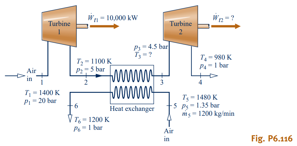
Air as an ideal gas flows through the turbine and heat exchanger arrangement shown in Fig. P6.116. Steady-state data are given on the figure. Stray heat transfer and kinetic and potential energy effects can be ignored. Determine
(a) temperature \(T_{3}\), in K.
(b) the power output of the second turbine, in kW.
(c) the rates of entropy production, each in kW/K, for the turbines and heat exchanger.
(d) Using the result of part (c), place the components in rank order, beginning with the component contributing most to inefficient operation of the overall system.
Questions & Answers
QUESTION:
Air as an ideal gas flows through the turbine and heat exchanger arrangement shown in Fig. P6.116. Steady-state data are given on the figure. Stray heat transfer and kinetic and potential energy effects can be ignored. Determine
(a) temperature \(T_{3}\), in K.
(b) the power output of the second turbine, in kW.
(c) the rates of entropy production, each in kW/K, for the turbines and heat exchanger.
(d) Using the result of part (c), place the components in rank order, beginning with the component contributing most to inefficient operation of the overall system.
ANSWER:
Step 1 of 4
Part a
We are required to calculate the temperature .
From the steady state energy balance rate equation, ignoring heat transfer and kinetic and potential energies.
From table A-22,
kJ/kg,
kJ/kg
Given, kW
Substitute these for ,
kg/s
kg/s
With the heat exchanger,
The energy rate balance equation is,
From table A-22,
kJ/kg,
kJ/kg
Substitute for ,
kJ/kg
kJ/kg
From table A-22, the corresponding temperature is 1301.5 K