Consider the falling mass in Example 3.1.1 and Figure 3.1.2. Find its speed and height as functions of time. How long will it take to reach (a) the platform and (b) the ground?
Read moreTable of Contents
1
Introduction
2
Dynamic Response and the Laplace Transform Method
3
Modeling of Rigid-Body Mechanical Systems
4
Spring and Damper Elements in Mechanical Systems
5
Block Diagrams, State-Variable Models, and Simulation Methods
6
Electrical and Electromechanical Systems
7
Fluid and Thermal Systems
8
System Analysis in the Time Domain
9
System Analysis in the Frequency Domain
10
Introduction to Feedback Control Systems
11
Control System Design and the Root Locus Plot
12
Compensator Design and the Bode Plot
13
Vibration Applications
Textbook Solutions for System Dynamics
Chapter 3 Problem 3.40
Question
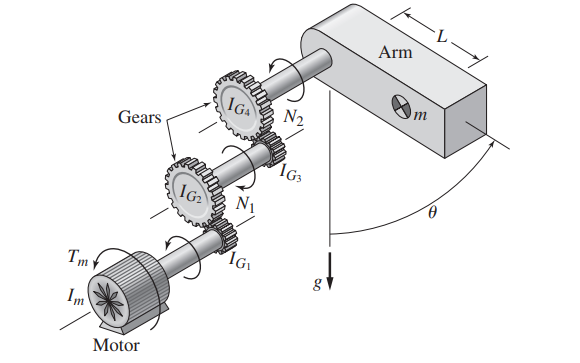
A single link of a robot arm is shown in Figure P3.40. The arm mass is m and its center of mass is located a distance L from the joint, which is driven by a
motor torque \(T_{m}\) through two pairs of spur gears. We model the arm as a pendulum with a concentrated mass m. Thus we take the arm’s moment of inertia \(I_{G}\) to be zero. The gear ratios are \(N_{1}=2\) (the motor shaft has the greater speed) and \(N_{2}=1.5\) (the shaft connected to the link has the slower speed). Obtain the equation of motion in terms of the angle \(\theta\), with \(T_{m}\) as the input. Neglect the shaft inertias relative to the other inertias. The given values for the motor and gear inertias are
\(\begin{array}{c} I_{m}=0.05 \mathrm{~kg} \cdot \mathrm{m}^{2} \quad I_{G_{1}}=0.025 \mathrm{~kg} \cdot \mathrm{m}^{2} \quad I_{G_{2}}=0.1 \mathrm{~kg} \cdot \mathrm{m}^{2} \\ I_{G_{3}}=0.025 \mathrm{~kg} \cdot \mathrm{m}^{2} \quad I_{G_{4}}=0.08 \mathrm{~kg} \cdot \mathrm{m}^{2} \end{array}\)
The values for the link are
m = 10 kg L = 0.3 m
Solution
The first step in solving 3 problem number 40 trying to solve the problem we have to refer to the textbook question: A single link of a robot arm is shown in Figure P3.40. The arm mass is m and its center of mass is located a distance L from the joint, which is driven by amotor torque \(T_{m}\) through two pairs of spur gears. We model the arm as a pendulum with a concentrated mass m. Thus we take the arm’s moment of inertia \(I_{G}\) to be zero. The gear ratios are \(N_{1}=2\) (the motor shaft has the greater speed) and \(N_{2}=1.5\) (the shaft connected to the link has the slower speed). Obtain the equation of motion in terms of the angle \(\theta\), with \(T_{m}\) as the input. Neglect the shaft inertias relative to the other inertias. The given values for the motor and gear inertias are\(\begin{array}{c} I_{m}=0.05 \mathrm{~kg} \cdot \mathrm{m}^{2} \quad I_{G_{1}}=0.025 \mathrm{~kg} \cdot \mathrm{m}^{2} \quad I_{G_{2}}=0.1 \mathrm{~kg} \cdot \mathrm{m}^{2} \\ I_{G_{3}}=0.025 \mathrm{~kg} \cdot \mathrm{m}^{2} \quad I_{G_{4}}=0.08 \mathrm{~kg} \cdot \mathrm{m}^{2} \end{array}\)The values for the link arem = 10 kg L = 0.3 m
From the textbook chapter Modeling of Rigid-Body Mechanical Systems you will find a few key concepts needed to solve this.
Visible to paid subscribers only
Step 3 of 7)Visible to paid subscribers only
Subscribe to view the
full solution
full solution
Title
System Dynamics 3
Author
William J Palm III
ISBN
9780073398068
A single link of a robot arm is shown in Figure P3.40. The
Chapter 3 textbook questions
-
Chapter 3: Problem 3 System Dynamics 3
-
Chapter 3: Problem 3 System Dynamics 3
A baseball is thrown horizontally from the pitcher’s mound with a speed of 90 mph. Neglect air resistance, and determine how far the ball will drop by the time it crosses home plate 60 ft away.
Read more -
Chapter 3: Problem 3 System Dynamics 3
For the mass shown in Figure 3.1.3b, m = 10 kg, \(\phi=25^{\circ}\), v(0) = 2 m/s, and \(\mu=0.3\). Determine whether the mass comes to rest if (a) \(f_{1}=100 \mathrm{~N}\) and (b) \(f_{1}=50 \mathrm{~N}\). If the mass comes to rest, compute the time at which it stops.
Read more -
Chapter 3: Problem 3 System Dynamics 3
A particle of mass m = 19 kg slides down a frictionless ramp starting from rest (see Figure P3.4). Suppose that \(\theta=30^{\circ}\), L = 5 m, and H = 2 m. Compute the distance D of the impact point.
Read more -
Chapter 3: Problem 3 System Dynamics 3
A particle of mass m slides down a frictionless ramp starting from rest (see Figure P3.4). The lengths L and H and the angle \(\theta\) are given. Derive an expression for the distance D of the impact point.
Read more -
Chapter 3: Problem 3 System Dynamics 3
A radar tracks the flight of a projectile (see Figure P3.6). At time t, the radar measures the horizontal component \(v_{x}(t)\) and the vertical component \(v_{y}(t)\) of the projectile’s velocity and its range R(t) and elevation \(\phi(t)\). Are these measurements sufficient to compute the horizontal distance D from the radar to the launch point of the projectile? If so, derive the expression for D as a function of g and the measured values \(v_{x}(t), v_{y}(t)\), R(t), and \(\phi(t)\).
Read more -
Chapter 3: Problem 3 System Dynamics 3
Table 3.2.1 gives the inertia \(I_{O}\) for a point mass in rotation. Suppose instead that a sphere of radius r is in rotation about a fixed point O a distance R from its center of mass. Find the inertia \(I_{O}\) of the sphere about the point O.
Read more -
Chapter 3: Problem 3 System Dynamics 3
A motor supplies a moment M to the pulley of radius \(R_{1}\) (Figure P3.8). A belt connects this pulley to pulley A. Pulleys A and B form a rigid body with a common hub. Ignore the inertias of the three pulleys. Determine the acceleration of the mass m in terms of M, m, \(R_{1}, R_{2}\), and \(R_{3}\).
Read more -
Chapter 3: Problem 3 System Dynamics 3
Figure P3.9 shows an inverted pendulum. Obtain the equation of motion in terms of the angle \(\phi\).
Read more -
Chapter 3: Problem 3 System Dynamics 3
The two masses shown in Figure P3.10 are released from rest. The mass of block A is 100 kg; the mass of block B is 20 kg. Ignore the masses of the pulleys and rope. Determine the acceleration of block A and of block B. Do they rise or fall?
Read more -
Chapter 3: Problem 3 System Dynamics 3
The motor in Figure P3.11 lifts the mass \(m_{L}\) by winding up the cable with a force \(F_{A}\). The center of pulley B is fixed. The pulley inertias are \(I_{B}\) and \(I_{C}\). Pulley C has a mass \(m_{C}\). Derive the equation of motion in terms of the speed \(v_{A}\) of point A on the cable with the force \(F_{A}\) as the input.
Read more -
Chapter 3: Problem 3 System Dynamics 3
Instead of using the system shown in Figure 3.2.6a to raise the mass \(m_{2}\), an engineer proposes to use two simple machines, the pulley and the inclined plane, to reduce the weight required to lift \(m_{2}\). The proposed design is shown in Figure P3.12. The pulley inertias are negligible. The available horizontal space limits the angle of the inclined plane to no less than \(30^{\circ}\). a. Suppose that the friction between the plane and the mass \(m_{2}\) is negligible. Determine the smallest value \(m_{1}\) can have to lift \(m_{2}\). Your answer should be a function of \(m_{2}\) and \(\theta\). b. In practice, the coefficient of dynamic friction \(\mu_{d}\) between the plane and the mass \(m_{2}\) is not known precisely. Assume that the system can be started to overcome static friction. For the value of \(m_{1}=m_{2} / 2\), how large can \(\mu_{d}\) be before m1 cannot lift \(m_{2}\)?
Read more -
Chapter 3: Problem 3 System Dynamics 3
An inextensible cable with a tension force f = 500 N is used to pull a two-wheeled cart on a horizontal surface (Figure P3.13). The wheels roll without slipping. The cart has a mass \(m_{c}=120 \mathrm{~kg}\). Each wheel has a radius \(R_{w}=0.4 \mathrm{~m}\) and an inertia \(I_{w}=1.5 \mathrm{~kg} \cdot \mathrm{m}^{2}\). Disregard the mass of the axle. The center of mass of the system is at point G. Compute the translational acceleration \(\dot{v}\) of the cart.
Read more -
Chapter 3: Problem 3 System Dynamics 3
Consider the cart shown in Figure P3.13. Suppose we model the wheels as solid disks. Then the wheel inertia is given by \(I_{w}=m_{w} R_{w}^{2} / 2\). How small must the wheel mass \(m_{w}\) be relative to the cart body mass \(m_{c}\) so that the two wheels increase the equivalent mass \(m_{e}\) by no more than 10%?
Read more -
Chapter 3: Problem 3 System Dynamics 3
Consider the spur gears shown in Figure P3.15, where \(I_{1}=0.3 \mathrm{~kg} \cdot \mathrm{m}^{2}\) and \(I_{2}=0.5 \mathrm{~kg} \cdot \mathrm{m}^{2}\). Shaft 1 rotates three times faster than shaft 2. The torques are given as \(T_{1}=0.5 \mathrm{~N} \cdot \mathrm{m}\) and \(T_{2}=-0.3 \mathrm{~N} \cdot \mathrm{m}\). Compute the equivalent inertia on shaft 2, and find the angular acceleration \(\dot{\omega}_{2}\).
Read more -
Chapter 3: Problem 3 System Dynamics 3
Consider the spur gears shown in Figure P3.15, where \(I_{1}=0.1 \mathrm{~kg} \cdot \mathrm{m}^{2}\) and \(I_{2}=2 \mathrm{~kg} \cdot \mathrm{m}^{2}\). Shaft 1 rotates twice as fast as shaft 2. The torques are given as \(T_{1}=10 \mathrm{~N} \cdot \mathrm{m}\) and \(T_{2}=0\). (a) Compute the angular acceleration \(\dot{\omega}_{1}\) assuming the shaft and gear inertias are negligible. (b) Suppose the gear on shaft 1 has an inertia \(0.005 \mathrm{~kg} \cdot \mathrm{m}^{2}\) and the gear on shaft 2 has an inertia 0.05 kg·m2. Compute the angular acceleration \(\dot{\omega}_{1}\).
Read more -
Chapter 3: Problem 3 System Dynamics 3
Derive the expression for the equivalent inertia \(I_{e}\) felt on the input shaft, for the spur gears shown in Figure P3.15, where the combined gear-shaft inertias are \(I_{s_{1}}\) and \(I_{s_{2}}\).
Read more -
Chapter 3: Problem 3 System Dynamics 3
Draw the free body diagrams of the two spur gears shown in Figure P3.15. Use the resulting equations of motion to show that \(T_{2}=N T_{1}\) if the gear inertias are negligible or if there is zero acceleration. Here \(T_{2}\) is taken to be the torque felt on shaft 2 due to the applied torque \(T_{1}\).
Read more -
Chapter 3: Problem 3 System Dynamics 3
The geared system shown in Figure P3.19 represents an elevator system. The motor has an inertia \(I_{1}\) and supplies a torque \(T_{1}\). Neglect the inertias of the gears, and assume that the cable does not slip on the pulley. Derive an expression for the equivalent inertia \(I_{e}\) felt on the input shaft (shaft 1). Then derive the dynamic model of the system in terms of the speed \(\omega_{1}\) and the applied torque \(T_{1}\). The pulley radius is R.
Read more -
Chapter 3: Problem 3 System Dynamics 3
Derive the expression for the equivalent inertia \(I_{e}\) felt on the input shaft, for the rack and pinion shown in Figure P3.20, where the shaft inertia is \(I_{s}\).
Read more -
Chapter 3: Problem 3 System Dynamics 3
Derive the expression for the equivalent inertia \(I_{e}\) felt on the input shaft, for the belt drive treated in Example 3.3.5, where the shaft inertias connected to the sprockets are \(I_{s_{1}}\) and \(I_{s_{2}}\).
Read more -
Chapter 3: Problem 3 System Dynamics 3
For the geared system shown in Figure P3.15, proper selection of the gear ratio N can maximize the load acceleration \(\dot{\omega}_{2}\) for a given motor and load. Note that the gear ratio is defined such that \(\omega_{1}=N \omega_{2}\). Assuming that the inertias \(I_{1}\) and \(I_{2}\) and the torques \(T_{1}\) and \(T_{2}\) are given, a. Derive the expression for the load acceleration \(\dot{\omega}_{2}\). b. Use calculus to determine the value of N that maximizes \(\dot{\omega}_{2}\).
Read more -
Chapter 3: Problem 3 System Dynamics 3
For the geared system shown in Figure P3.23, assume that shaft inertias and the gear inertias \(I_{1}, I_{2}\), and \(I_{3}\) are negligible. The motor and load inertias in \(\mathrm{kg} \cdot \mathrm{m}^{2}\) are \(I_{4}=0.03 \quad I_{5}=0.15\) The speed ratios are \(\frac{\omega_{1}}{\omega_{2}}=\frac{\omega_{2}}{\omega_{3}}=1.6\) Derive the system model in terms of the speed \(\omega_{3}\), with the applied torque T as the input.
Read more -
Chapter 3: Problem 3 System Dynamics 3
For the geared system discussed in Problem 3.23, shown in Figure P3.23, the inertias are given in \(\mathrm{kg} \cdot \mathrm{m}^{2}\) as \(\begin{array}{c} I_{1}=10^{-3} \quad I_{2}=3.84 \times 10^{-3} \quad I_{3}=0.0148 \\ I_{4}=0.03 \quad I_{5}=0.15 \end{array}\) The speed ratios are \(\frac{\omega_{1}}{\omega_{2}}=\frac{\omega_{2}}{\omega_{3}}=1.6\) Derive the system model in terms of the speed \(\omega_{3}\), with the applied torque T as the input. The shaft inertias are negligible.a
Read more -
Chapter 3: Problem 3 System Dynamics 3
The geared system shown in Figure P3.25 is similar to that used in some vehicle transmissions. The speed ratios (which are the ratios of the gear radii) are \(\frac{\omega_{2}}{\omega_{1}}=3 \quad \frac{\omega_{3}}{\omega_{2}}=\frac{3}{5} \quad \frac{\omega_{4}}{\omega_{3}}=\frac{13}{11}\) a. Determine the overall speed ratio \(\omega_{4} / \omega_{1}\). b. Derive the equation of motion in terms of the velocity \(\omega_{4}\), with the torque \(T_{1}\) as the input. Neglect the inertias of the gears and the shafts.
Read more -
Chapter 3: Problem 3 System Dynamics 3
Consider the rack-and-pinion gear shown in Figure P3.20. Use the free-body diagram method to obtain the expression for the acceleration \(\ddot{x}\) in terms of the given quantities: R, T , m, and I.
Read more -
Chapter 3: Problem 3 System Dynamics 3
For the conveyor system shown in Figure P3.27, the reducer reduces the motor speed by a factor of 2:1. The motor inertia is \(I_{1}=0.003 \mathrm{~kg} \cdot \mathrm{m}^{2}\). Discount the inertias of the reducer and the tachometer, which is used to measure the speed for control purposes. Ignore the inertias of the two sprockets, the chain, and all shafts. The only significant masses and inertias are the inertias of the four drive wheels \(\left(0.01 \mathrm{~kg} \cdot \mathrm{m}^{2} \text { each }\right)\), the two drive chains (6 kg each), and the load mass (8 kg). The radius of sprocket 1 is 0.04 m, that of sprocket 2 is 0.12 m. The drive wheel has a radius of 0.1 m. The load friction torque measured at the drive shaft is \(0.9 \mathrm{~N} \cdot \mathrm{m}\) a. Derive the equation of motion of the conveyor in terms of the motor velocity, with the motor torque \(T_{1}\) as the input. b. Suppose the motor torque is constant at \(1.2 \mathrm{~N} \cdot \mathrm{m}\). Determine the resulting motor angular acceleration and load acceleration.
Read more -
Chapter 3: Problem 3 System Dynamics 3
The lead screw (also called a power screw or a jack screw) is used to convert the rotation of a motor shaft into a translational motion of the mass m (see Figure P3.28). For one revolution of the screw, the mass translates a distance L (called the screw lead ). As felt on the motor shaft, the translating mass appears as an equivalent inertia. Use kinetic energy equivalence to derive an expression for the equivalent inertia. Let \(I_{s}\) be the inertia of the screw.
Read more -
Chapter 3: Problem 3 System Dynamics 3
At time t = 0, the operator of the road roller disengages the transmission so that the vehicle rolls down the incline (see Figure P3.29). Determine an expression for the vehicle’s speed as a function of time. The two rear wheels weigh 500 lb each and have a radius of 4 ft. The front wheel weighs 800 lb and has a radius of 2 ft. The vehicle body weighs 9000 lb. Assume the wheels roll without slipping.
Read more -
Chapter 3: Problem 3 System Dynamics 3
Derive the equation of motion of the block of mass \(m_{1}\) in terms of its displacement x (see Figure P3.30). The friction between the block and the surface is negligible. The pulley has negligible inertia and negligible friction. The cylinder has a mass \(m_{2}\) and rolls without slipping.
Read more -
Chapter 3: Problem 3 System Dynamics 3
Assume the cylinder in Figure P3.31 rolls without slipping. Neglect the mass of the pulleys and derive the equation of motion of the system in terms of the displacement x.
Read more -
Chapter 3: Problem 3 System Dynamics 3
A conveyor drive system to produce translation of the load is shown in Figure P3.27a. The reducer is a gear pair that reduces the motor speed by a factor of 10:1. The motor inertia is \(I_{1}=0.002 \mathrm{~kg} \cdot \mathrm{m}^{2}\). The reducer inertia as felt on the motor shaft is \(I_{2}=0.003 \mathrm{~kg} \cdot \mathrm{m}^{2}\). Neglect the inertia of the tachometer, which is used to measure the speed for control purposes. The properties of the remaining elements are given here. Sprockets: Sprocket 1: radius = 0.05 m mass = 0.9 kg Sprocket 2: radius = 0.15 m mass = 8.9 kg Chain mass: 10.7 kg Drive shaft: radius = 0.04 m mass = 2.2 kg Drive wheels (four of them): radius = 0.2 m mass = 8.9 kg each Drive chains (two of them): mass = 67 kg each Load friction torque measured at the drive shaft: 54 N · m Load mass: 45 kg a. Derive the equation of motion of the conveyor in terms of the motor velocity \(\omega_{1}\), with the motor torque \(T_{1}\) as the input. b. Suppose the motor torque is constant at \(10 \mathrm{~N} \cdot \mathrm{m}\). Determine the resulting motor velocity \(\omega_{1}\) and load velocity v as functions of time, assuming the system starts from rest. c. The profile of a desired velocity for the load is shown in Figure P3.27b, where \(v_{0}=1 \mathrm{~m} / \mathrm{s}, t_{1}=t_{3}=0.5 \mathrm{~s}\), and \(t_{2}=2 \mathrm{~s}\). Use the equation of motion found in part (a) to compute the required motor torque for each part of the profile.
Read more -
Chapter 3: Problem 3 System Dynamics 3
A person pushes a roller of radius R and inertia \(m R^{2} / 2\), with a force f applied at an angle of \(\phi\) to the horizontal (see Figure P3.33). The roller weighs 800 N and has a diameter of 0.4 m. Assume the roller does not slip. Derive the equation of motion in terms of (a) the rotational velocity \(\omega\) of the roller and (b) the displacement x.
Read more -
Chapter 3: Problem 3 System Dynamics 3
A slender rod 1.4 m long and of mass 20 kg is attached to a wheel of radius 0.05 m and negligible mass, as shown in Figure P3.34. A horizontal force f is applied to the wheel axle. Derive the equation of motion in terms of \(\theta\). Assume the wheel does not slip.
Read more -
Chapter 3: Problem 3 System Dynamics 3
A slender rod 1.4 m long and of mass 20 kg is attached to a wheel of mass 3 kg and radius 0.05 m, as shown in Figure P3.34. A horizontal force f is applied to the wheel axle. Derive the equation of motion in terms of \(\theta\). Assume the wheel does not slip.
Read more -
Chapter 3: Problem 3 System Dynamics 3
Consider the rolling cylinder treated in Example 3.4.1 and shown in Figure P3.36. Assume now that the no-slip condition is not satisfied, so that the cylinder slips while it rolls. Derive expression for the translational acceleration \(a_{G_{x}}\) and the angular acceleration \(\alpha\). The coefficient of dynamic friction is \(\mu_{d}\).
Read more -
Chapter 3: Problem 3 System Dynamics 3
A hoop of mass m and radius r starts from rest and rolls down an incline at an angle \(\theta\). The hoop’s inertia is given by \(I_{G}=m r^{2}\). The static friction coefficient is \(\mu_{s}\). Determine the acceleration of the center of mass \(a_{G_{x}}\) and the angular acceleration \(\alpha\). Assume that the hoop rolls without bouncing or slipping. Use two approaches to solve the problem: (a) Use the moment equation about the mass center G and (b) use the moment equation about the contact point P. (c) Obtain the frictional condition required for the hoop to roll without slipping.
Read more -
Chapter 3: Problem 3 System Dynamics 3
The pendulum shown in Figure P3.38 consists of a slender rod weighing 3 lb and a block weighing 10 lb. a. Determine the location of the center of mass. b. Derive the equation of motion in terms of \(\theta\).
Read more -
Chapter 3: Problem 3 System Dynamics 3
The scale shown in Figure P3.39 measures the weight mg of an object placed on the scale, by using a counterweight of mass \(m_{c}\). Friction in the pivot point at A causes the pointer to eventually come to rest at an angle \(\theta\), which indicates the measured value of the weight mg. The angle \(\beta\) has a fixed value that depends on the shape of the scale arm. (a) Neglect the friction in the pivot and neglect the mass of the scale arm, and obtain the scale’s equation of motion. (b) Find the equilibrium relation between the weight mg and the angle \(\theta\). (c) Find the weight mg if \(m_{c}=5 \mathrm{~kg}, L_{1}=0.2 \mathrm{~m}, L_{2}=0.15 \mathrm{~m}, \beta=30^{\circ}\), and \(\theta=20^{\circ}\).
Read more -
Chapter 3: Problem 3 System Dynamics 3
A single link of a robot arm is shown in Figure P3.40. The arm mass is m and its center of mass is located a distance L from the joint, which is driven by a motor torque \(T_{m}\) through two pairs of spur gears. We model the arm as a pendulum with a concentrated mass m. Thus we take the arm’s moment of inertia \(I_{G}\) to be zero. The gear ratios are \(N_{1}=2\) (the motor shaft has the greater speed) and \(N_{2}=1.5\) (the shaft connected to the link has the slower speed). Obtain the equation of motion in terms of the angle \(\theta\), with \(T_{m}\) as the input. Neglect the shaft inertias relative to the other inertias. The given values for the motor and gear inertias are \(\begin{array}{c} I_{m}=0.05 \mathrm{~kg} \cdot \mathrm{m}^{2} \quad I_{G_{1}}=0.025 \mathrm{~kg} \cdot \mathrm{m}^{2} \quad I_{G_{2}}=0.1 \mathrm{~kg} \cdot \mathrm{m}^{2} \\ I_{G_{3}}=0.025 \mathrm{~kg} \cdot \mathrm{m}^{2} \quad I_{G_{4}}=0.08 \mathrm{~kg} \cdot \mathrm{m}^{2} \end{array}\) The values for the link are m = 10 kg L = 0.3 m
Read more -
Chapter 3: Problem 3 System Dynamics 3
It is required to determine the maximum acceleration of the rear-wheel-drive vehicle shown in Figure P3.41. The vehicle mass is 1700 kg, and its dimensions are \(L_{A}=1.2 \mathrm{~m}, L_{B}=1.1 \mathrm{~m}\), and H = 0.5 m. Assume that each front wheel experiences the same reaction force \(N_{A} / 2\). Similarly, each rear wheel experiences the same reaction force \(N_{B} / 2\). Thus the traction force \(\mu_{s} N_{B}\) is the total traction force due to both driving wheels. Assume that the mass of the wheels is small compared with the total vehicle mass; this assumption enables us to treat the vehicle as a translating rigid body with no rotating parts.
Read more -
Chapter 3: Problem 3 System Dynamics 3
Figure P3.42 illustrates a pendulum with a base that moves horizontally. This is a simple model of an overhead crane carrying a suspended load with cables. The load mass is m, the cable length is L, and the base acceleration is a(t). Assuming that the cable acts like a rigid rod, derive the equation of motion in terms of \(\theta\) with a(t) as the input
Read more -
Chapter 3: Problem 3 System Dynamics 3
Figure P3.43 illustrates a pendulum with a base that moves. The base acceleration is a(t). Derive the equation of motion in terms of \(\theta\) with a(t) as the input. Neglect the mass of the rod.
Read more -
Chapter 3: Problem 3 System Dynamics 3
The overhead trolley shown in Figure P3.44 is used to transport beams in a factory. The beam is rectangular, with a length of L. It is desired to limit the trolley horizontal acceleration a so that the beam does not swing too much. The beam starts from rest with \(\theta(0)=0\). (a) Use a small angle approximation and determine the maximum value of \(\theta\) if L = 3 m and \(a=2 \mathrm{~m} / \mathrm{s}^{2}\). Once you obtain an answer, use it to check the validity of the small angle approximation. (b) Solve the problem given in part (a), using symbolic values for L, a, and g. Does the answer depend on all three variables? If not, explain why.
Read more -
Chapter 3: Problem 3 System Dynamics 3
The analysis of the personal transporter in Example 3.5.6 assumed that the driving force f was the given input. Instead, model the system with the assumption that the input is the total torque \(T_{w}\) applied by the motor to the wheel-axle unit. The wheel radius is R. Obtain the equations of motion in terms of x and \(\phi\) with T and \(T_{w}\) as the input.
Read more -
Chapter 3: Problem 3 System Dynamics 3
The “sky crane” shown on the text cover was a novel solution to the problem of landing the 2000 lb Curiosity rover on the surface of Mars. Curiosity hangs from the descent stage by 60-foot-long nylon tethers (Figure P3.46a). The descent stage uses its thrusters to hover as the rover is lowered to the surface. Thus the rover behaves like a pendulum whose base is moving, just like the pendulum analyzed in Problem 3.42 (see Figure P3.42). However, problem 3.42 neglected the mass of the base, but the descent stage also has significant mass. So a better model is the one shown in Figure P3.46b. The rover mass is \(m_{r}\), the descent stage mass is \(m_{d}\), and the net horizontal component of the thruster forces is f. Among other simplifications, this model does not take into account vertical motion and any rotational motion. Derive the equations of motion of the system in terms of the angle \(\theta\) and the displacement x, with the force f as the given input.
Read more