The copper shaft shown in Figure P7.46 consists of two
Chapter , Problem 7.46(choose chapter or problem)
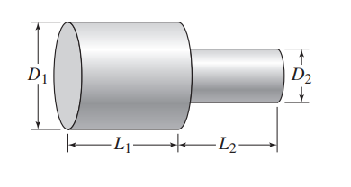
The copper shaft shown in Figure P7.46 consists of two cylinders with the following dimensions: \(L_{1}=10 \mathrm{~mm}, L_{2}=5 \mathrm{~mm}, D_{1}=2 \mathrm{~mm}\), and \(D_{2}=1.5 \mathrm{~mm}\). The shaft is insulated around its circumference so that heat transfer occurs only in the axial direction.
(a) Compute the thermal resistance of each section of the shaft and of the total shaft. Use the following value for the conductivity of copper: \(k=400 \mathrm{~W} / \mathrm{m} \cdot{ }^{\circ} \mathrm{C}\).
(b) Compute the heat flow rate in the axial direction if the temperature difference across the endpoints of the shaft is \(30^{\circ} \mathrm{C}\).
Unfortunately, we don't have that question answered yet. But you can get it answered in just 5 hours by Logging in or Becoming a subscriber.
Becoming a subscriber
Or look for another answer