Solved: The circuit shown in Fig. P7.99 is known as an astable multivibrator and finds
Chapter 7, Problem 7.99(choose chapter or problem)
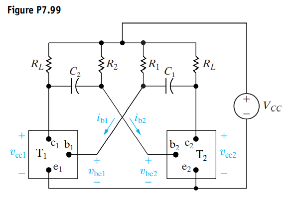
The circuit shown in Fig. P7.99 is known as an astable multivibrator and finds wide application in pulse circuits. The purpose of this problem is to relate the charging and discharging of the capacitors to the operation of the circuit. The key to analyzing the circuit is to understand the behavior of the ideal transistor switches \(\mathrm{T}_{1}\) and \(\mathrm{T}_{2}\) The circuit is designed so that the switches automatically alternate between ON and OFF. When \(\mathrm{T}_{1}\) is OFF, \(\mathrm{T}_{2}\) is ON and vice versa.Thus in the analysis of this circuit, we assume a switch is either ON or OFF. We also assume that the ideal transistor switch can change its state instantaneously. In other words, it can snap from OFF to ON and vice versa.When a transistor switch is ON, (1) the base current \(i_{\mathrm{b}}\) is greater than zero, (2) the terminal voltage \(v_{\text {be }}\) is zero, and (3) the terminal voltage \(v_{\text {ce }}\) is zero. Thus, when a transistor switch is ON, it presents a short circuit between the terminals b,e and c,e. When a transistor switch is OFF, (1) the terminal voltage \(v_{\text {be }}\) is negative, (2) the base current is zero, and (3) there is an open circuit between the terminals c,e. Thus when a transistor switch is OFF, it presents an open circuit between the terminals b,e and c,e. Assume that \(\mathrm{T}_{2}\) has been ON and has just snapped OFF, while \(\mathrm{T}_{1}\) has been OFF and has just snapped ON. You may assume that at this instance, \(C_{2}\) is charged to the supply voltage \(V_{\mathrm{CC}}\), and the charge on \(C_{1}\) is zero. Also assume \(C_{1}=C_{2}\) and \(R_{1}=R_{2}=10 R_{L}\).
a) Derive the expression for \(v_{\mathrm{be} 2}\) during the interval that \(\mathrm{T}_{2}\) is OFF.
b) Derive the expression for \(v_{\mathrm{ce} 2}\) during the interval that \(\mathrm{T}_{2}\) is OFF.
c) Find the length of time \(\mathrm{T}_{2}\) is OFF.
d) Find the value of \(v_{\mathrm{ce} 2}\) at the end of the interval that \(\mathrm{T}_{2}\) is OFF.
e) Derive the expression for \(i_{\mathrm{b} 1}\) during the interval that \(\mathrm{T}_{2}\) is OFF.
f) Find the value of \(i_{\mathrm{b} 1}\) at the end of the interval that \(\mathrm{T}_{2}\) is OFF.
g) Sketch \(v_{\mathrm{ce} 2}\) versus t during the interval that \(\mathrm{T}_{2}\) is OFF.
h) Sketch \(i_{\mathrm{b} 1}\) versus t during the interval that \(\mathrm{T}_{2}\) is OFF.
Unfortunately, we don't have that question answered yet. But you can get it answered in just 5 hours by Logging in or Becoming a subscriber.
Becoming a subscriber
Or look for another answer