Solution Found!
Steam-driven power generators rotate at a constant speed
Chapter 9, Problem 47(choose chapter or problem)
Steam-driven power generators rotate at a constant speed via a governor that maintains constant steam pressure in the turbine. In addition, automatic generation control (AGC) or load frequency control (LFC) is added to ensure reliability and consistency despite load variations or other disturbances that can affect the distribution line frequency output. A specific turbine-governor system can be described only using the block diagram of Figure P9.1 in which G(s) = \(G_c(s) G_g(s) G_t(s) G_m(s)\), where (Khodabakhshian, 2005)
\(G_g(s)\) = \(\frac{1}{0.2 s+1}\) is the governor's transfer function
\(G_t(s)\) = \(\frac{1}{0.5 s+1}\) is the turbine transfer function
\(G_m(s)\) = \(\frac{1}{10 s+0.8}\) represents the machine and load \(G_c(s)\) is the LFC compensation to be designed
a. Assuming \(G_c(s)\) = K, find the value of K that will result in a dominant pole with \(\zeta\) = 0.7. Obtain the corresponding \(T_s\).
b. Design a PID controller to obtain the same damping factor as in Part a, but with a settling time of 2 seconds and zero steady-state error to step input commands.
c. Verify your results using a MATLAB simulation.
Questions & Answers
(1 Reviews)
QUESTION:
Steam-driven power generators rotate at a constant speed via a governor that maintains constant steam pressure in the turbine. In addition, automatic generation control (AGC) or load frequency control (LFC) is added to ensure reliability and consistency despite load variations or other disturbances that can affect the distribution line frequency output. A specific turbine-governor system can be described only using the block diagram of Figure P9.1 in which G(s) = \(G_c(s) G_g(s) G_t(s) G_m(s)\), where (Khodabakhshian, 2005)
\(G_g(s)\) = \(\frac{1}{0.2 s+1}\) is the governor's transfer function
\(G_t(s)\) = \(\frac{1}{0.5 s+1}\) is the turbine transfer function
\(G_m(s)\) = \(\frac{1}{10 s+0.8}\) represents the machine and load \(G_c(s)\) is the LFC compensation to be designed
a. Assuming \(G_c(s)\) = K, find the value of K that will result in a dominant pole with \(\zeta\) = 0.7. Obtain the corresponding \(T_s\).
b. Design a PID controller to obtain the same damping factor as in Part a, but with a settling time of 2 seconds and zero steady-state error to step input commands.
c. Verify your results using a MATLAB simulation.
ANSWER:Step 1 of 3
The open loop transfer function is \(G(s)=\frac{1}{(s+0.08)(s+2)(s+5)}\)
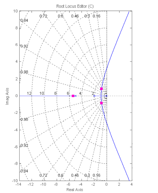
The root locus for the system is shown below with \(G_{c}(s)=7.02\), the system has a \(\xi=0.7\) damping factor for the dominant pole which is located at \(-0.847 \pm j 0.849\). The third pole is located at \(-5.4\), so the second order approximation applies. The resulting settling time \(\left(T_{s}=5.16 \mathrm{~s}\right)\) with a peak overshoot of \(4.2 \%\).
Reviews
Review this written solution for 230649) viewed: 628 isbn: 9781118170519 | Control Systems Engineering - 7 Edition - Chapter 9 - Problem 47
Thank you for your recent purchase on StudySoup. We invite you to provide a review below, and help us create a better product.
No thanks, I don't want to help other students