Solution Found!

Consider the voltage divider circuit shown in Figure P 3.3-13. The resistor R represents
Chapter 3, Problem P 3.3-13(choose chapter or problem)
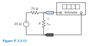
Consider the voltage divider circuit shown in Figure P 3.3-13. The resistor R represents a temperature sensor. The resistance R, in \(\Omega\), is related to the temperature T, in \({ }^{\circ} \mathrm{C}\), by the equation
\(R=50+\frac{1}{2} T\)
(a) Determine the meter voltage, \(v_{\mathrm{m}}\), corresponding to temperatures \(0^{\circ} \mathrm{C}, 75^{\circ} \mathrm{C}\), and \(100^{\circ} \mathrm{C}\).
(b) Determine the temperature T corresponding to the meter voltages 8 V, 10 V, and 15 V.
Questions & Answers
QUESTION:
Consider the voltage divider circuit shown in Figure P 3.3-13. The resistor R represents a temperature sensor. The resistance R, in \(\Omega\), is related to the temperature T, in \({ }^{\circ} \mathrm{C}\), by the equation
\(R=50+\frac{1}{2} T\)
(a) Determine the meter voltage, \(v_{\mathrm{m}}\), corresponding to temperatures \(0^{\circ} \mathrm{C}, 75^{\circ} \mathrm{C}\), and \(100^{\circ} \mathrm{C}\).
(b) Determine the temperature T corresponding to the meter voltages 8 V, 10 V, and 15 V.
ANSWER:
Step 1 of 4:
It is desired that the output power absorbed by