Solution Found!

The input to the circuit shown in Figure DP 10-6 is the voltage source voltage vs t 10
Chapter 10, Problem DP10-6(choose chapter or problem)
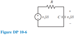
The input to the circuit shown in Figure DP 10-6 is the voltage source voltage
\(v_{\mathrm{s}}(t)=10 \cos (1000 t) \mathrm{V}\)
The output is the steady-state capacitor voltage
\(v_{\mathrm{o}}(t)=A \cos (1000 t+\theta) \mathrm{V}\)
(a) Specify values for R and C such that \(\theta=-30^{\circ}\). Determine the resulting value of A.
(b) Specify values for R and C such that A = 5 V. Determine the resulting values of \(\theta\).
(c) Is it possible to specify values for R and C such that A = 4 and \(\theta=-60^{\circ}\)? (If not, justify your answer. If so, specify R and C.)
(d) Is it possible to specify values of R and C such that A = 7.07 V and \(\theta=-45^{\circ}\)? (If not, justify your answer. If so, specify R and C.)
Questions & Answers
QUESTION:
The input to the circuit shown in Figure DP 10-6 is the voltage source voltage
\(v_{\mathrm{s}}(t)=10 \cos (1000 t) \mathrm{V}\)
The output is the steady-state capacitor voltage
\(v_{\mathrm{o}}(t)=A \cos (1000 t+\theta) \mathrm{V}\)
(a) Specify values for R and C such that \(\theta=-30^{\circ}\). Determine the resulting value of A.
(b) Specify values for R and C such that A = 5 V. Determine the resulting values of \(\theta\).
(c) Is it possible to specify values for R and C such that A = 4 and \(\theta=-60^{\circ}\)? (If not, justify your answer. If so, specify R and C.)
(d) Is it possible to specify values of R and C such that A = 7.07 V and \(\theta=-45^{\circ}\)? (If not, justify your answer. If so, specify R and C.)
ANSWER:
Step 1 of 7
Considered voltages 


The equivalent circuit diagram in frequency domain shown on Figure below.
