
The input to the circuit shown in Figure P 13.3-4 is the source voltage vs(t), and the
Chapter 13, Problem P13.3-4(choose chapter or problem)
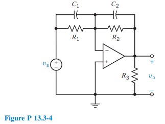
The input to the circuit shown in Figure P 13.3-4 is the source voltage \(v_s(t)\), and the response is the voltage across \(R_3, v_0(t)\). Determine \(\mathbf{H}(\omega)\) and sketch the Bode diagram.
Unfortunately, we don't have that question answered yet. But you can get it answered in just 5 hours by Logging in or Becoming a subscriber.
Becoming a subscriber
Or look for another answer