
The input to the circuit shown in Figure P 13.3-5a is the voltage vi(t) of the
Chapter 13, Problem P13.3-5(choose chapter or problem)
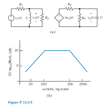
The input to the circuit shown in Figure P 13.3-5a is the voltage \(v_1(t)\) of the independent voltage source. The output is the voltage \(v_{\mathrm{o}}(t)\) across the capacitor. Design this circuit to have the Bode plot shown in Figure P 13.3-5b.
Hint: First, show that the network function of the circuit is
\(\begin{aligned} \mathbf{H}(\omega) & =\frac{\mathbf{V}_{\mathrm{o}}(\omega)}{\mathbf{V}_{\mathrm{i}}(\omega)} \\ & =\frac{j \omega\left(\frac{A L R_4}{R_1\left(R_3+R_4\right)}\right)}{\left(1+j \omega \frac{L\left(R_1+R_2\right)}{R_1 R_2}\right)\left(1+j \omega \frac{C R_3 R_4}{R_3+R_4}\right)} \end{aligned}\)
Unfortunately, we don't have that question answered yet. But you can get it answered in just 5 hours by Logging in or Becoming a subscriber.
Becoming a subscriber
Or look for another answer