
Figure P 13.3-11 shows a circuit and corresponding asymptotic magnitude Bode plot. The
Chapter 13, Problem P13.3-11(choose chapter or problem)
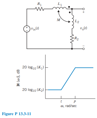
Figure P 13.3-11 shows a circuit and corresponding asymptotic magnitude Bode plot. The input to this circuit shown is the source voltage \(v_{\mathrm{in}}(t)\), and the response is the voltage \(v_{\mathrm{o}}(t)\). The component values are \(R_1=80 \Omega, R_2=20 \Omega, L_1=0.03 \mathrm{H}\), \(L_2=0.07 \mathrm{H}\), and \(M=0.01 \mathrm{H}\). Determine the values of \(K_1, K_2\), p, and z.
Unfortunately, we don't have that question answered yet. But you can get it answered in just 5 hours by Logging in or Becoming a subscriber.
Becoming a subscriber
Or look for another answer