Solution Found!

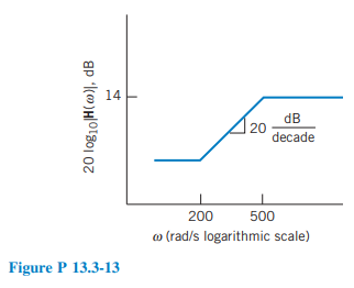
Design a circuit that has the asymptotic magnitude Bode plot shown in Figure P 13.3-13
Chapter 13, Problem P13.3-13(choose chapter or problem)
Design a circuit that has the asymptotic magnitude Bode plot shown in Figure P 13.3-13.
Questions & Answers
QUESTION:
Design a circuit that has the asymptotic magnitude Bode plot shown in Figure P 13.3-13.
ANSWER:
Step 1 of 4
Obtain the network function of the circuit using the given magnitude Bode plot. Consider the magnitude Bode plot from the left to right. We can see that there are two corner frequencies:
1- The first is at 
2-The second is at 
3- There is a constant