Solution Found!
In Fig. 27-73, R1 ! 5.00 0, R2 ! 10.0 0, R3 ! 15.0 0, C1 !
Chapter , Problem 80(choose chapter or problem)
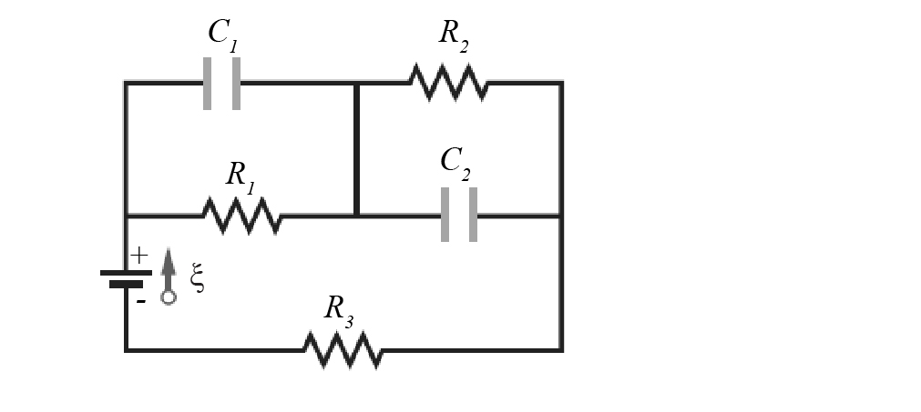
In Fig. 27-73, R1 ! 5.00 0, R2 ! 10.0 0, R3 ! 15.0 0, C1 ! 5.00 mF, C2 ! 10.0 mF, and the ideal battery has emf # ! 20.0 V.Assuming that the circuit is in the steady state,what is the total energy stored in the two capacitors? C1C2R2R1R3+Figure 27-73 80.
Questions & Answers
QUESTION:
In Fig. 27-73, R1 ! 5.00 0, R2 ! 10.0 0, R3 ! 15.0 0, C1 ! 5.00 mF, C2 ! 10.0 mF, and the ideal battery has emf # ! 20.0 V.Assuming that the circuit is in the steady state,what is the total energy stored in the two capacitors? C1C2R2R1R3+Figure 27-73 80.
ANSWER:Problem 80
In Fig. 27-73, R1=5.00 0, R2 =10.0, R3=15.0, C1=5.00 mF, C2=10.0 mF, and the ideal battery has emf = 20.0V. Assuming that the circuit is in the steady state, what is the total energy stored in the two capacitors?
Step by Step Solution
Step 1 of 6
At the time of steady state, the current flows through the resistors only, so the current will not pass through the capacitors.
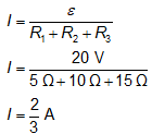
The expression for the current in the circuit in the loop is given as follows:

For the current