Represent the electrical network shown in Figure P3.1 in state space, where \(v_o(t)\) is the output. [Section: 3.4]
Read moreTable of Contents
1
INTRODUCTION
2
MODELING IN THE FREQUENCY DOMAIN
3
MODELING IN THE TIME DOMAIN
4
TIME RESPONSE
5
REDUCTION OF MULTIPLE SUBSYSTEMS
6
STABILITY
7
STEADY-STATE ERRORS
8
ROOT LOCUS TECHNIQUES
9
DESIGN VIA ROOT LOCUS
10
FREQUENCY RESPONSE TECHNIQUES
11
DESIGN VIA FREQUENCY RESPONSE
12
DESIGN VIA STATE SPACE
13
DIGITAL CONTROL SYSTEMS
Textbook Solutions for Control Systems Engineering
Chapter 3 Problem 5
Question
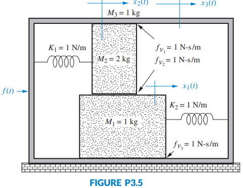
Represent the translational mechanical system shown in Figure P3.5 in state space, where \(x_1(t)\) is the output. [Section: 3.4]
Solution
The first step in solving 3 problem number 5 trying to solve the problem we have to refer to the textbook question: Represent the translational mechanical system shown in Figure P3.5 in state space, where \(x_1(t)\) is the output. [Section: 3.4]
From the textbook chapter MODELING IN THE TIME DOMAIN you will find a few key concepts needed to solve this.
Visible to paid subscribers only
Step 3 of 7)Visible to paid subscribers only
Subscribe to view the
full solution
full solution
Title
Control Systems Engineering 7
Author
Norman J. Nise
ISBN
9781118170519
Represent the translational mechanical system shown in
Chapter 3 textbook questions
-
Chapter 3: Problem 1 Control Systems Engineering 7
-
Chapter 3: Problem 2 Control Systems Engineering 7
Represent the electrical network shown in Figure P3.2 in state space, where \(i_R(t)\) is the output. [Section: 3.4]
Read more -
Chapter 3: Problem 3 Control Systems Engineering 7
Find the state-space representation of the network shown in Figure P3.3 if the output is \(v_o(t)\). [Section: 3.4]
Read more -
Chapter 3: Problem 4 Control Systems Engineering 7
Represent the system shown in Figure P3.4 in state space where the output is \(x_3(t)\). [Section: 3.4]
Read more -
Chapter 3: Problem 5 Control Systems Engineering 7
Represent the translational mechanical system shown in Figure P3.5 in state space, where \(x_1(t)\) is the output. [Section: 3.4]
Read more -
Chapter 3: Problem 6 Control Systems Engineering 7
Represent the rotational mechanical system shown in Figure P3.6 in state space, where \(\theta_1(t)\) is the output. [Section: 3.4]
Read more -
Chapter 3: Problem 7 Control Systems Engineering 7
Represent the system shown in Figure P3.7 in state space where the output is \(\theta_L(t)\). [Section: 3.4]
Read more -
Chapter 3: Problem 8 Control Systems Engineering 7
Show that the system of Figure 3.7 in the text yields a fourth-order transfer function if we relate the displacement of either mass to the applied force, and a third-order one if we relate the velocity of either mass to the applied force. [Section: 3.4]
Read more -
Chapter 3: Problem 9 Control Systems Engineering 7
Find the state-space representation in phase-variable form for each of the systems shown in Figure P3.8. [Section: 3.5]
Read more -
Chapter 3: Problem 10 Control Systems Engineering 7
Repeat Problem 9 using MATLAB. [Section: 3.5]
Read more -
Chapter 3: Problem 11 Control Systems Engineering 7
For each system shown in Figure P3.9, write the state equations and the output equation for the phase-variable representation. [Section: 3.5]
Read more -
Chapter 3: Problem 12 Control Systems Engineering 7
Repeat Problem 11 using MATLAB. [Section: 3.5]
Read more -
Chapter 3: Problem 13 Control Systems Engineering 7
Represent the following transfer function in state space. Give your answer in vector-matrix form. [Section: 3.5] \(T(s)=\frac{s(s+2)}{(s+1)\left(s^2+2 s+5\right)}\)
Read more -
Chapter 3: Problem 14 Control Systems Engineering 7
Find the transfer function G(s)=Y(s)/R(s) for each of the following systems represented in state space: [Section: 3.6] (a) \(\begin{aligned} \dot{\mathbf{x}} & =\left[\begin{array}{rrr} 0 & 1 & 0 \\ 0 & 0 & 1 \\ -3 & -2 & -5 \end{array}\right] \mathbf{x}+\left[\begin{array}{r} 0 \\ 0 \\ 10 \end{array}\right] r \\ y & =\left[\begin{array}{lll} 1 & 0 & 0 \end{array}\right] \mathbf{x} \end{aligned}\) (b) \(\begin{aligned} \dot{\mathbf{x}} & =\left[\begin{array}{rrr} 2 & -3 & -8 \\ 0 & 5 & 3 \\ -3 & -5 & -4 \end{array}\right] \mathbf{x}+\left[\begin{array}{l} 1 \\ 4 \\ 6 \end{array}\right] r \\ y & =\left[\begin{array}{lll} 1 & 3 & 6 \end{array}\right] \mathbf{x} \\\) (c) \(\dot{\mathbf{x}} & =\left[\begin{array}{rrr} 3 & -5 & 2 \\ 1 & -8 & 7 \\ -3 & -6 & 2 \end{array}\right] \mathbf{x}+\left[\begin{array}{r} 5 \\ -3 \\ 2 \end{array}\right] r \\ y & =\left[\begin{array}{lll} 1 & -4 & 3 \end{array}\right] \mathbf{x} \end{aligned}\)
Read more -
Chapter 3: Problem 15 Control Systems Engineering 7
Use MATLAB to find the transfer function, G(s)=Y(s)/R(s), for each of the following systems represented in state space: [Section: 3.6] (a) \(\dot{\mathbf{x}}=\left[\begin{array}{rrrr}0 & 1 & 5 & 0 \\ 0 & 0 & 1 & 0 \\ 0 & 0 & 0 & 1 \\ -7 & -9 & -2 & -3\end{array}\right] \mathbf{x}+\left[\begin{array}{l}0 \\ 5 \\ 8 \\ 2\end{array}\right] r\) \(y=\left[\begin{array}{llll} 1 & 3 & 6 & 6 \end{array}\right] \mathbf{x}\) (b) \(\begin{aligned} & \dot{\mathbf{x}}=\left[\begin{array}{rrrrr} 3 & 1 & 0 & 4 & -2 \\ -3 & 5 & -5 & 2 & -1 \\ 0 & 1 & -1 & 2 & 8 \\ -7 & 6 & -3 & -4 & 0 \\ -6 & 0 & 4 & -3 & 1 \end{array}\right] \mathbf{x}+\left[\begin{array}{l} 2 \\ 7 \\ 8 \\ 5 \\ 4 \end{array}\right] r \\ & y=\left[\begin{array}{lllll} 1 & -2 & -9 & 7 & 6 \end{array}\right] \mathbf{x} \end{aligned}\)
Read more -
Chapter 3: Problem 16 Control Systems Engineering 7
Repeat Problem 15 using MATLAB, the Symbolic Math Toolbox, and Eq. (3.73). [Section: 3.6]
Read more -
Chapter 3: Problem 17 Control Systems Engineering 7
A missile in flight, as shown in Figure P3.10, is subject to four forces: thrust, lift, drag, and gravity. The missile flies at an angle of attack, \(\alpha\), from its longitudinal axis, creating lift. For steering, the body angle from vertical, \(\phi\), is controlled by rotating the engine at the tail. The transfer function relating the body angle, \(\phi\), to the angular displacement, \(\delta\), of the engine is of the form \(\frac{\Phi(s)}{\delta(s)}=\frac{K_a s+K_b}{K_3 s^3+K_2 s^2+K_1 s+K_0}\) Represent the missile steering control in state space. [Section: 3.5]
Read more -
Chapter 3: Problem 18 Control Systems Engineering 7
Given the dc servomotor and load shown in Figure P3.11, represent the system in state space, where the state variables are the armature current, \(i_a\), load displacement, \(\theta_L\), and load angular velocity, \(\omega_L\). Assume that the output is the angular displacement of the armature. Do not neglect armature inductance. [Section: 3.4]
Read more -
Chapter 3: Problem 19 Control Systems Engineering 7
Consider the mechanical system of Figure P3.12. If the spring is nonlinear, and the force, \(F_s\), required to stretch the spring is \(F_s=2 x_1^2\), represent the system in state space linearized about \(x_1=1\) if the output is \(x_2\). [Section: 3.7]
Read more -
Chapter 3: Problem 20 Control Systems Engineering 7
Image-based homing for robots can be implemented by generating heading command inputs to a steering system based on the following guidance algorithm. Suppose the robot shown in Figure P3.13(a) is to go from point R to a target, point T, as shown in Figure P3.13(b). If \(\mathbf{R}_x, \mathbf{R}_y\), and \(\mathbf{R}_z\) are vectors from the robot to each landmark, X, Y, Z, respectively, and \(\mathbf{T}_x, \mathbf{T}_y\), and \(\mathbf{T}_z\) are vectors from the target to each landmark, respectively, then heading commands would drive the robot to minimize \(\mathbf{R}_x-\mathbf{T}_x, \mathbf{R}_y-\mathbf{T}_y\), and \(\mathbf{R}_z-\mathbf{T}_z\) simultaneously, since the differences will be zero when the robot arrives at the target (Hong, 1992). If Figure P3.13(c) represents the control system that steers the robot, represent each block-the controller, wheels, and vehicle-in state space. An animation PowerPoint presentation (PPT) demonstrating this system is available for instructors at www.wiley.com/college/nise. See Robot. [Section: 3.5]
Read more -
Chapter 3: Problem 21 Control Systems Engineering 7
Modern robotic manipulators that act directly upon their target environments must be controlled so that impact forces as well as steady-state forces do not damage the targets. At the same time, the manipulator must provide sufficient force to perform the task. In order to develop a control system to regulate these forces,the robotic manipulator and target environment must be modeled. Assuming the model shown in Figure P3.14, represent in state space the manipulator and its environment under the following conditions (Chiu, 1997). [Section: 3.5] (a) The manipulator is not in contact with its target environment. (b) The manipulator is in constant contact with its target environment.
Read more -
Chapter 3: Problem 22 Control Systems Engineering 7
In the past, Type-1 diabetes patients had to inject themselves with insulin three to four times a day. New delayed-action insulin analogues such as insulin Glargine require a single daily dose. A similar procedure to the one described in the Pharmaceutical Drug Absorption case study of this chapter is used to find a model for the concentration-time evolution of plasma for insulin Glargine. For a specific patient, state-space model matrices are given by (Tarín, 2007) \(\begin{aligned} & \mathbf{A}=\left[\begin{array}{ccc} -0.435 & 0.209 & 0.02 \\ 0.268 & -0.394 & 0 \\ 0.227 & 0 & -0.02 \end{array}\right] ; \quad \mathbf{B}=\left[\begin{array}{l} 1 \\ 0 \\ 0 \end{array}\right] ; \\ & \mathbf{C}=\left[\begin{array}{lll} 0.0003 & 0 & 0 \end{array}\right] ; \quad \mathbf{D}=0 \end{aligned}\) where the state vector is given by \(\mathbf{x}=\left[\begin{array}{l} x_1 \\ x_2 \\ x_3 \end{array}\right]\) . The state variables are \(x_1=\) insulin amount in plasma compartment \(x_2=\) insulin amount in liver compartment \(x_3=\) insulin amount in interstitial (in body tissue) compartment The system’s input is u= external insulin flow. The system’s output is y= plasma insulin concentration. (a) Find the system’s transfer function. (b) Verify your result using MATLAB.
Read more -
Chapter 3: Problem 23 Control Systems Engineering 7
A linear, time-invariant model of the hypothalamic pituitary-adrenal axis of the endocrine system with five state variables has been proposed as follows (Kyrylov, 2005): \(\begin{aligned} & \frac{d x_0}{d t}=a_{00} x_0+a_{02} x_2+d_0 \\ & \frac{d x_1}{d t}=a_{10} x_0+a_{11} x_1+a_{12} x_2 \\ & \frac{d x_2}{d t}=a_{20} x_0+a_{21} x_1+a_{22} x_2+a_{23} x_3+a_{24} x_4 \\ & \frac{d x_3}{d t}=a_{32} x_2+a_{33} x_3 \\ & \frac{d x_4}{d t}=a_{42} x_2+a_{44} x_4 \end{aligned}\) where each of the state variables represents circulatory concentrations as follows: \(x_0\)= corticotropin-releasing hormone \(x_1\)= corticotropin \(x_2\)= free cortisol \(x_3\)= albumin-bound cortisol \(x_4\)= corticosteroid-binding globulin \(d_0\)= an external generating factor Express the system in the form \(\dot{\mathbf{x}}=\mathbf{A x}+\mathbf{B u}\).
Read more -
Chapter 3: Problem 24 Control Systems Engineering 7
In this chapter, we described the state-space representation of single-input, single-output systems. In general, systems can have multiple inputs and multiple outputs. An autopilot is to be designed for a submarine as shown in Figure P3.15 to maintain a constant depth under severe wave disturbances. We will see that this system has two inputs and two outputs and thus the scaler u becomes a vector, u, and the scaler y becomes a vector, y, in the state equations. It has been shown that the system’s linearized dynamics under neutral buoyancy and at a given constant speed are given by (Liceaga-Castro, 2009): \(\begin{aligned} \dot{\mathbf{x}} & =\mathbf{A x}+\mathbf{B u} \\ \mathbf{y} & =\mathbf{C} \mathbf{x} \end{aligned}\) where \(\mathbf{x}=\left[\begin{array}{l} w \\ q \\ z \\ \theta \end{array}\right] ; \quad \mathbf{y}=\left[\begin{array}{c} z \\ \theta \end{array}\right] ; \quad \mathbf{u}=\left[\begin{array}{c} \delta_B \\ \delta_S \end{array}\right]\) \(\begin{aligned} & \mathbf{A}=\left[\begin{array}{cccc} -0.038 & 0.896 & 0 & 0.0015 \\ 0.0017 & -0.092 & 0 & -0.0056 \\ 1 & 0 & 0 & -3.086 \\ 0 & 1 & 0 & 0 \end{array}\right] ; \\ & \mathbf{B}=\left[\begin{array}{cc} -0.0075 & -0.023 \\ 0.0017 & -0.0022 \\ 0 & 0 \\ 0 & 0 \end{array}\right] ; \quad \mathbf{C}=\left[\begin{array}{cccc} 0 & 0 & 1 & 0 \\ 0 & 0 & 0 & 1 \end{array}\right] \end{aligned}\) and where w = the heave velocity q = the pitch rate z = the submarine depth \(\theta\) = the pitch angle \(\delta_B\) = the bow hydroplane angle \(\delta_S\) = the stern hydroplane angle Since this system has two inputs and two outputs, four transfer functions are possible. (a) Use MATLAB to calculate the system’s matrix transfer function. (b) Using the results from Part a, write the transfer function \(\frac{z(s)}{\delta_B(s)}, \frac{z(s)}{\delta_S(s)}, \frac{\theta(s)}{\delta_B(s)}\), and \(\frac{\theta(\mathrm{s})}{\delta_S(s)}\).
Read more -
Chapter 3: Problem 25 Control Systems Engineering 7
Experiments to identify precision grip dynamics between the index finger and thumb have been performed using a ball-drop experiment. A subject holds a device with a small receptacle into which an object is dropped, and the response is measured (Fagergren, 2000). Assuming a step input, it has been found that the response of the motor subsystem together with the sensory system is of the form \(G(s)=\frac{Y(s)}{R(s)}=\frac{s+c}{\left(s^2+a s+b\right)(s+d)}\) Convert this transfer function to a state-space representation.
Read more -
Chapter 3: Problem 26 Control Systems Engineering 7
State-space representations are, in general, not unique. One system can be represented in several possible ways. For example, consider the following systems: (a) \(\begin{aligned} \dot{x} & =-5 x+3 u \\ y & =7 x \end{aligned}\) (b) \(\begin{aligned} {\left[\begin{array}{l} \dot{x}_1 \\ \dot{x}_2 \end{array}\right] } & =\left[\begin{array}{rr} -5 & 0 \\ 0 & -1 \end{array}\right]\left[\begin{array}{l} x_1 \\ x_2 \end{array}\right]+\left[\begin{array}{l} 3 \\ 1 \end{array}\right] u \\ y & =\left[\begin{array}{ll} 7 & 0 \end{array}\right]\left[\begin{array}{l} x_1 \\ x_2 \end{array}\right] \end{aligned}\) (c) \(\begin{aligned} {\left[\begin{array}{l} \dot{x}_1 \\ \dot{x}_2 \end{array}\right] } & =\left[\begin{array}{rr} -5 & 0 \\ 0 & -1 \end{array}\right]\left[\begin{array}{l} x_1 \\ x_2 \end{array}\right]+\left[\begin{array}{l} 3 \\ 0 \end{array}\right] u \\ y & =\left[\begin{array}{ll} 7 & 3 \end{array}\right]\left[\begin{array}{l} x_1 \\ x_2 \end{array}\right] \end{aligned}\) Show that these systems will result in the same transfer function. We will explore this phenomenon in more detail in Chapter 5.
Read more -
Chapter 3: Problem 27 Control Systems Engineering 7
Figure P3.16 shows a schematic description of the global carbon cycle (Li, ) . In the figure, \(m_A(t)\) represents the amount of carbon in gigatons \((\mathrm{GtC})\) present in the atmosphere of earth; \(m_V(t)\) the amount in vegetation; \(m_s(t)\) the amount in soil; \(m_{S O}(t)\) the amount in surface ocean; and \(m_{I D O}(t)\) the amount in intermediate and deep ocean reservoirs. Let \(u_E(t)\) stand for the human generated \(\mathrm{CO}_2\) emissions (GtC/yr). From the figure, the atmospheric mass balance in the atmosphere can be expressed as: \(\begin{aligned} \frac{d m_A}{d t}(t)= & u_E(t)-\left(k_{O 1}+k_{L 1}\right) m_A(t)+k_{L 2} m_V(t) \\ & +k_{O 2} m_{S O}(t)+k_{L 4} m_S(t) \end{aligned}\) where the k's are exchange coefficients \(\left(\mathrm{yr}^{-1}\right)\). (a) Write the remaining reservoir mass balances. Namely, write equations for \(\frac{d m_{S O}(t)}{d t}, \frac{d m_{I D O}(t)}{d t}, \frac{d m_V(t)}{d t}\), and \(\frac{d m_S(t)}{d t}\) (b) Express the system in state-space form.
Read more -
Chapter 3: Problem 28 Control Systems Engineering 7
Given the photovoltaic system described in Problem 65 in Chapter 2 (Agee, 2012) and defining the following state variables, system input and output as \(y=x_1=\theta_m\), \(x_2=\dot{\theta}_m, x_3=i_a\), and \(u=e_a\), write a state-space representation of the system in the form \(\dot{\mathbf{x}}=\mathbf{A x}+\mathbf{B} u\), \(\mathbf{y}=\mathbf{C x}\).
Read more -
Chapter 3: Problem 29 Control Systems Engineering 7
A single-pole oil cylinder valve contains a spool that regulates hydraulic pressure, which is then applied to a piston that drives a load. The transfer function relating piston displacement, \(X_p(s)\) to spool displacement from equilibrium, \(X_v(s)\), is given by (Q u, 2010): \(G(s)=\frac{X_p(s)}{X_v(s)}=\frac{K_q \omega_h^2 / A_1}{s\left(s^2+2 \varsigma \omega_h s+\omega_h^2\right)}\) where \(A_1=\) effective area of a the valve's chamber, \(K_q=\) rate of change of the load flow rate with a change in displacement, and \(\omega_h=\) the natural frequency of the hydraulic system. Find the state-space representation of the system, where the state variables are the phase variables associated with the piston.
Read more -
Chapter 3: Problem 30 Control Systems Engineering 7
Figure P3.17 shows a free-body diagram of an inverted pendulum, mounted on a cart with a mass, M. The pendulum has a point mass, m, concentrated at the upper end of a rod with zero mass, a length, l, and a frictionless hinge. A motor drives the cart, applying a horizontal force, u(t). A gravity force, mg, acts on m at all times. The pendulum angle relative to the y-axis, \(\theta\), its angular speed, \(\dot{\theta}^{\prime}\), the horizontal position of the cart, x, and its speed, \(x^{\prime}\), were selected to be the state variables. The state-space equations derived were heavily nonlinear. \({ }^{14}\) They were then linearized around the stationary point, \(\mathbf{x}_{\mathbf{0}}=\mathbf{0}\) and \(u_0=0\), and manipulated to yield the following open-loop model written in perturbation form: \(\frac{d}{d t} \delta \mathbf{x}=\mathbf{A} \delta \mathbf{x}+\mathbf{B} \delta u\) However, since \(\mathbf{x}_{\mathbf{0}}=\mathbf{0}\) and \(u_0=0\), then let: \(\mathbf{x}=\mathbf{x}_0+\delta \mathbf{x}= \delta \mathbf{x}\) and \(u=u_0+\delta u=\delta u\). Thus the state equation may be rewritten as (Prasad, 2012): \(\dot{\mathbf{x}}=\mathbf{A} \mathbf{x}+\mathbf{B} u\) where \(\mathbf{A}=\left[\begin{array}{cccc} 0 & 1 & 0 & 0 \\ \frac{(M+m) g}{M l} & 0 & 0 & 0 \\ 0 & 0 & 0 & 1 \\ -\frac{m g}{M} & 0 & 0 & 0 \end{array}\right] \text { and } \mathbf{B}=\left[\begin{array}{c} 0 \\ \frac{-1}{M l} \\ 0 \\ \frac{1}{M} \end{array}\right]\) Assuming the output to be the horizontal position of \(m=x_m=x+l \sin \theta=x+l \theta\) for a small angle, \(\theta\), the output equation becomes: \(y=l \theta+x=\mathbf{C x}=\left[\begin{array}{llll} l & 0 & 1 & 0 \end{array}\right]\left[\begin{array}{l} \theta \\ \dot{\theta} \\ x \\ \dot{x} \end{array}\right]\) Given that: \(M=2.4 \mathrm{~kg}, m=0.23 \mathrm{~kg}\), \(I=0.36 \mathrm{~m}, g=9.81 \mathrm{~m} / \mathrm{s}^2\), use MATLAB to find the transfer function, \(G(s)=Y(s) / U(s)=X_m(s) / U(s)\)
Read more -
Chapter 3: Problem 31 Control Systems Engineering 7
Control of HIV/AIDS. Problem 67 in Chapter 2 introduced a model for HIV infection. If retroviral drugs, RTIs and PIs as discussed in Problem 22inChapter 1, are used, the model is modified as follows (Craig, 2004): \(\begin{aligned} & \frac{d T}{d t}=s-d T-\left(1-u_1\right) \beta T v \\ & \frac{d T^*}{d t}=\left(1-u_1\right) \beta T v-\mu T^* \\ & \frac{d v}{d t}=\left(1-u_2\right) k T^*-c v \end{aligned}\) where \(0 \leq u_1 \leq 1,0 \leq u_2 \leq 1\) represent the effectiveness of the RTI and PI medication, respectively. (a) Obtain a state-space representation of the HIV/AIDS model by linearizing the equations about the \(\left(T_0, T_0^*, \quad v_0\right)=\left(\frac{c \mu}{\beta k}, \frac{s}{\mu}-\frac{c d}{\beta k}, \frac{s k}{c \mu}-\frac{d}{\beta}\right)\) equilibrium with \(u_{10}=u_{20}=0\). This equilibrium represents the asymptomatic HIV-infected patient. Note that each one of the above equations is of the form \(\dot{x}_i=f_i\left(x_i, u_1, u_2\right), i=1,2,3\). (b) If Matrices A and B are given by \(\mathbf{A}=\left[\begin{array}{lll}\frac{\partial f_1}{\partial x_1} & \frac{\partial f_1}{\partial x_2} & \frac{\partial f_1}{\partial x_3} \\ \frac{\partial f_2}{\partial x_1} & \frac{\partial f_2}{\partial x_2} & \frac{\partial f_2}{\partial x_3} \\ \frac{\partial f_3}{\partial x_1} & \frac{\partial f_3}{\partial x_2} & \frac{\partial f_3}{\partial x_3}\end{array}\right]_{T_0, T_0^*, v_0} ; \quad \mathbf{B}=\left[\begin{array}{ll}\frac{\partial f_1}{\partial u_1} & \frac{\partial f_1}{\partial u_2} \\ \frac{\partial f_2}{\partial u_1} & \frac{\partial f_2}{\partial u_2} \\ \frac{\partial f_3}{\partial u_1} & \frac{\partial f_3}{\partial u_2}\end{array}\right]_{T_0, T_0^*, v_0}\) and we are interested in the number of free HIV viruses as the system's output, \(\mathbf{C}=\left[\begin{array}{lll} 0 & 0 & 1 \end{array}\right]\) show that \(\mathbf{A}=\left[\begin{array}{crc} -\left(d+\beta v_0\right) & 0 & -\beta T_0 \\ \beta v_0 & -\mu & \beta T_0 \\ 0 & k & -c \end{array}\right] ; \quad \mathbf{B}=\left[\begin{array}{cc} \beta T_0 v_0 & 0 \\ -\beta T_0 v_0 & 0 \\ 0 & -k T_0^* \end{array}\right]\) (c) Typical parameter values and descriptions for the HIV/AIDS model are shown in the following table. Substitute the values from the table into your model and write as \(\begin{aligned} & \dot{\mathbf{x}}=\mathbf{A} \mathbf{x}+\mathbf{B u} \\ & \mathbf{y}=\mathbf{C x} \end{aligned}\)
Read more -
Chapter 3: Problem 32 Control Systems Engineering 7
Hybrid vehicle. For Problem 23 in Chapter 1 we developed the functional block diagrams for the cruise control of serial, parallel, and split-power hybrid electric vehicles (HEV). Those diagrams showed that the engine or electric motor or both may propel the vehicle. When electric motors are the sole providers of the motive force, the forward paths of all HEV topologies are similar. In general, such a forward path can be represented (Preitl, 2007) by a block diagram similar to the one of Figure P3.18. Assume the motor to be an armature-controlled dc motor. In this diagram, \(K_A\) is the power amplifier gain; \(G_e(s)\) is the transfer function of the motor electric circuit and consists of a series inductor and resistor, \(L_a\) and \(R_a\), respectively; \(K_t\) is the motor torque constant; \(J_{\text {tot }}\), is the sum of the motor inertia, \(J_m\), the inertias of the vehicle, \(J_{v e h}\), and the two driven wheels, \(J_w\), both of which are reflected to the motor shaft; \(k_f\) is the coefficient of viscous friction; and \(k_b\) is the back emf constant. The input variables are \(u_c(t)\), the command voltage from the electronic control unit and \(T_c(t)\), the load torque. The output variables in this block diagram are the motor angular speed, \(\omega(t)\), and its armature current, \(I_a(t)\). (a) Write the basic time-domain equations that characterize the relationships between the state, input, and output variables for the block diagram of Figure P3.18, given that the state variables are the motor armature current, \(I_a(t)\), and angular speed, \(\omega(t)\). (b) Write the resulting state-space equations and then represent them in matrix form. Regard the load torque \(T_c(t)\) as an extra input to the system. Thus, in your resulting state-space representation, the system will have two inputs and two outputs.
Read more -
Chapter 3: Problem 33 Control Systems Engineering 7
Parabolic trough collector. A transfer function model from fluid flow to fluid temperature for a parabolic trough collector was introduced in Problem 69, Chapter 2. A more detailed model for the response of this system is given under specific operation conditions (Camacho, 2012) by: \(\frac{H}{Q}(s)=\frac{137.2 \times 10^{-6}}{s^2+0.0224 s+196 \times 10^{-6}} e^{-39 s}\) Find an appropriate state-space representation for the system.
Read more